Compressor and dynamics
Zygos
Zygos
The gain reduction is not a curve applied to the signal: it emerges from the model of the element producing it - a photocell with memory, a remote-cutoff valve, a JFET used as a voltage-controlled resistor, a log/antilog VCA pair, a diode bridge, and a linear reference.
v1.1.0

betadownload and try
Perpetual licence · 12 months of updates · full trial before you buy
In beta, and you try all of it
This is not a cut-down version: it is the complete instrument. We are asking you to use it and tell us what does not add up.
3 seconds at −18 dBFS · the clock restarts at every launch
v1.1.0
Every licence covers both formats. Until a licence file is activated the plugin runs in trial: the first 10 minutes of each session are clean, then a 3-second noise burst at -18 dBFS every 3 minutes, and offline renders are degraded.
At the defaults, Zygos is a bit-exact null.
The signal comes out identical, sample by sample. A mastering compressor that colours even at rest is not acceptable, and the exact null is the net that stops a colouration being introduced by inattention rather than by decision.
The cells
6 gain cells, and a chassis they all share.
Each cell is modelled at component level and receives its control in dB, as real log/antilog stages do. Distortion, memory and programme dependence are consequences of the model, not effects added afterwards.
Optical and valve
The photocell has memory: its conductance relaxes along time constants that depend on the light it has seen, so how long it was held down changes how it lets go. In the valve the reduction is the bias shift itself, and the distortion grows as it compresses without anyone driving it.
JFET and VCA
In the JFET cell distortion rises with reduction, and a linearisation control runs from clean to gritty. The VCA is the surgical one: its distortion lives at low levels and disappears on peaks - the exact opposite of a FET.
Diode bridge and linear
The diode bridge distorts more and more as the reduction grows, then levels off, and a mismatch control brings back the even harmonics. The linear cell is a mathematically exact multiplier: the reference, and the default.
Who it is for
For deciding how a compressor should behave, not just how hard.
Threshold and ratio are the same everywhere. The interesting choice is which element is doing the compressing.
Mastering
Zero latency at the factory values, a bit-exact null at rest, and a linear-phase crossover when the application needs one.
Mixing
62 factory presets organised by source, 6 bands when a single band is not enough, and a full sidechain equaliser.
Sound design
Oversampling up to 8x on the cell alone, with antiderivative anti-aliasing, so the cell can be pushed until it breaks and still be listened to.
The detector
3 detectors, and a real feedback topology.
Peak, true RMS and a hybrid, each with a complete sidechain equaliser in front. Both feedforward and feedback topologies are available - and the feedback one is a real loop, not a softened curve pretending to be one.
- Peak, true RMS, hybrid - with a full sidechain equaliser
- Feedforward and feedback, the latter a genuine loop
- External sidechain input

Multiband
Up to 6 bands, and two kinds of crossover.
True Phase is an infinite-impulse-response crossover with zero latency; Linear Phase is a 1023-tap finite-impulse-response one. The choice is a trade between latency and phase behaviour, and it is yours to make rather than ours to assume.
- 6 bands maximum, each with its own cell
- True Phase crossover: zero latency
- Linear Phase crossover: 1023 taps

The chassis
Power-supply sag and a thermal state - shared by every band.
Compressing draws current. Under reduction the supply voltage sags, the effective threshold rises, and the compressor reduces a little less exactly while it works hardest, recovering with the time constant of the reservoir: that is where the breathing of real hardware comes from. The rail is one per instance, so two bands compressing together pull it down further than one - a multiband setting behaves like one machine rather than like 6 plugins in a row. Input and output transformers, with core size and hysteresis, are optional and off at the factory. At rest the supply does not move a single sample.

The panel
Four views, one bar, nothing hidden.
The top bar is the one shared by the whole effects line: presets with their arrows, undo and redo, A | B, BYPASS, OPTIONS. Under it the six cells as six keys, each with the physical description of its component; the transfer curve, computed with the same static curve as the engine, beside a polar view of the two-capacitor R-C network; a 1.4 s history of reduction, output and input with IN and OUT meters per channel. Four views - BAND, DETECT, SIDECHAIN, CELL LAB - share the left side, while OUTPUT stays on the right whichever is open: that is why all 130 parameters have a control on the panel.
- Exact bypass: the output is the delayed input, bit for bit, whatever the iron, the safety or the trims are doing
- A | B: two complete copies of the sound, saved with the session
- Undo and redo by gesture, 64 steps
- Panel of 1200 x 860, scalable from 50 to 200 %

What is measured
You pay only for what you ask for.
Latency is zero samples at the factory values. Oversampling applies to the cell alone rather than to the whole plugin, and the linear-phase crossover is the only thing that adds delay - and only when you choose it.
All 130 parameters are automatable and all of them are reachable from the panel: nothing is hidden behind a menu that automation can reach but a person cannot. The bit-exact null at the defaults is verified rather than asserted, and so is the bypass: at any setting, the bypassed output is the input delayed by the declared latency, bit for bit.


Specifications
Keep looking
Looking for something else?
The other instruments and effects are one click away.
Downloads
Try Zygos
Each download is the Windows installer, a single .msi file. It installs for all users, so Windows asks for administrator rights; under each release there is also the .exe installer, inside a ZIP.
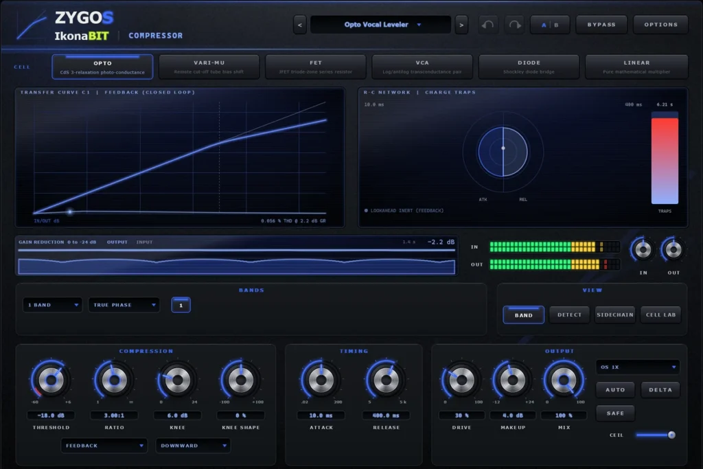
Zygos
Gain reduction that comes from a model
The gain reduction is not a curve applied to the signal: it emerges from the model of the element producing it - a photocell with memory, a remote-cutoff valve, a JFET used as a voltage-controlled resistor, a log/antilog VCA pair, a diode bridge, and a linear reference.
ikonabit-Zygos-1.1.0 beta
VST3Standalone
File names and previous versions (1)
- ikonabit-Zygos-1.1.0.msi
ikonabit-Zygos-1.0.0 beta
VST3Standalone